How Closed-Loop Hall Current Transducers Improve Dynamic Current Feedback in Inverters and Industrial Drives
How Closed-Loop Hall Current Transducers Improve Dynamic Current Feedback in Inverters and Industrial Drives
Inverters, variable-frequency drives, servo systems, industrial power converters, and renewable energy equipment depend on fast and reliable current feedback to control power semiconductor switching and protect the complete system. Closed-loop Hall current transducers provide isolated measurement of AC, DC, pulse, and complex current waveforms while combining good linearity with fast dynamic response. For OEM designers and procurement teams, choosing the right sensor can influence control-loop stability, motor performance, converter efficiency, fault response, and long-term equipment reliability.
1. Fast Current Feedback Helps Inverters and Drives Control Power More Precisely
Modern inverters and industrial drives regulate electrical power by switching semiconductor devices at high speed. The controller continuously adjusts this switching according to current, voltage, torque, speed, and other feedback signals. Current measurement therefore becomes part of the control loop rather than simply a monitoring function.
A slow or inaccurate current sensor can delay the controller's response to changing load conditions. In motor-drive applications, this may influence torque control and dynamic performance. In inverters and converters, poor current feedback can affect current regulation, protection thresholds, and power conversion efficiency.
Variable-frequency motor drives
Servo control systems
Solar and energy storage inverters
UPS and industrial power converters
Battery charging and discharging equipment
High-power automation systems
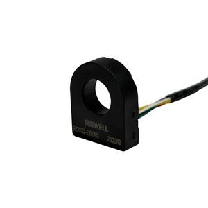
Closed-loop Hall current transducers are well suited to these applications because they can measure bidirectional AC and DC current while electrically isolating the primary conductor from the low-voltage control circuit. Their feedback architecture also helps improve linearity and dynamic performance compared with simpler open-loop sensing methods.
For procurement teams, response time and bandwidth should therefore be considered together with nominal current range. A sensor that can measure the required current but cannot respond fast enough to the converter's dynamic conditions may limit overall system performance.
2. Linearity, Offset and Bandwidth Determine the Quality of the Control Signal
Dynamic current measurement requires more than fast response. The signal also needs to remain accurate across positive current, negative current, low load, rated load, and rapid transitions. Several sensor characteristics therefore contribute to the quality of the feedback signal.
Helps the controller maintain predictable current regulation across a wide operating range.
Reduces measurement error around zero current and improves bidirectional current feedback.
Allows the sensor to follow rapid current changes and complex switching waveforms more accurately.
Protects control electronics while allowing measurement of high-current and high-voltage power circuits.
Temperature drift is another important consideration. Industrial drives and inverters may operate close to power semiconductor modules, busbars, heat sinks, and other heat-generating components. If sensor offset or gain changes excessively with temperature, the controller may receive different current information as the system warms up.
OEM engineers should therefore evaluate current sensor performance across the expected temperature range instead of relying only on a room-temperature accuracy value. Dynamic testing with pulse current, rapid current reversal, and real switching waveforms can also provide a better indication of application suitability.
Signal quality should be considered at system level. The current transducer, output cable, ADC, control board, grounding, shielding, and software filtering all influence final feedback performance. A high-quality sensor delivers the greatest value when the complete measurement chain is designed correctly.
3. What OEM Buyers Should Check Before Selecting Closed-Loop Hall Current Transducers
Once a current transducer has been integrated into an inverter or drive platform, replacing it later may require PCB changes, busbar redesign, calibration updates, controller tuning, and new validation. Procurement teams should therefore evaluate both sensor performance and supplier capability before approving a device for production.
Rated AC/DC current range
Linearity across the measurement range
Zero-current offset
Response time
Bandwidth
Temperature drift
Electrical isolation
Output signal compatibility
Mechanical aperture and mounting
Batch-to-batch consistency
Sample testing should use the actual inverter or drive whenever possible. Engineers can evaluate the sensor during acceleration, deceleration, load changes, current reversal, startup, overload, and other dynamic operating conditions. This reveals performance issues that may not appear during static DC testing.
Mechanical integration should also be checked carefully. Busbar size, conductor position, sensor aperture, PCB location, cooling airflow, connector orientation, and nearby magnetic sources can all influence installation and repeatability.
For high-volume OEM programs, supplier process control is equally important. Variations in magnetic materials, Hall elements, compensation circuits, calibration, and assembly can create unit-to-unit differences. Buyers should review production testing, traceability, calibration methods, and long-term component availability.
The lowest unit price is therefore not always the lowest system cost. A sensor with better dynamic accuracy and manufacturing consistency can reduce tuning time, calibration, field troubleshooting, and product redesign. For inverter and drive manufacturers, stable current feedback can directly contribute to stronger final equipment performance.
Conclusion
Closed-loop Hall current transducers improve dynamic current feedback in inverters and industrial drives by combining isolated AC/DC measurement with fast response, good linearity, and stable bidirectional sensing. These characteristics help controllers respond more accurately to changing loads, current reversal, pulse conditions, and high-frequency power conversion. For OEM procurement teams, the best sensor should be selected according to linearity, offset, bandwidth, response time, temperature drift, electrical isolation, mechanical integration, and production consistency. By working with a supplier that provides stable calibration and reliable mass production, inverter and drive manufacturers can reduce development risk and build more responsive and dependable power-control systems.