How Conductor Size and Contact Design Affect Voltage Drop in 250A CCS2 DC Charging Cables
How Conductor Size and Contact Design Affect Voltage Drop in 250A CCS2 DC Charging Cables
In high-power DC fast charging, the charging cable is not simply a connection between the charger and the vehicle. It is part of the complete power-delivery system, and its conductor resistance, connector contact resistance, terminal structure, and thermal design can directly influence voltage drop, heat generation, charging efficiency, and long-term reliability. For 250A CCS2 charging applications, even relatively small resistance differences can become significant because of the high current involved. For EV charger manufacturers and procurement teams, understanding how conductor size and contact design affect real operating performance is essential when comparing charging cable suppliers.
1. Larger Conductors Help Reduce Resistance, Voltage Drop and Cable Heating
When current flows through a charging cable, electrical resistance creates a voltage drop between the charging station and the vehicle. The same resistance also produces heat. At 250A, this effect becomes much more important than in lower-current AC charging applications, which is why conductor design is one of the first specifications buyers should evaluate.
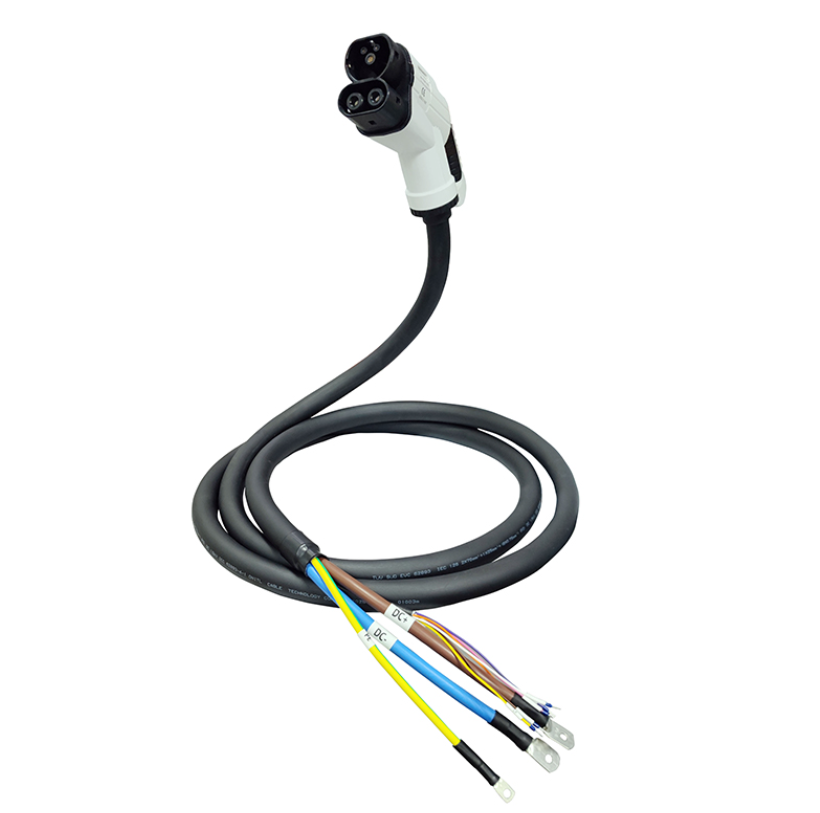
Conductor resistance is influenced by material conductivity, cross-sectional area, cable length, strand construction, operating temperature, and manufacturing consistency. Increasing conductor cross-sectional area generally reduces resistance, helping lower both voltage drop and power loss during charging.
Conductor cross-sectional area
Copper material and conductivity
Total charging cable length
Stranding structure and flexibility
Operating temperature
Production consistency between cable batches
However, simply increasing conductor size is not always the best answer. Larger conductors increase cable diameter, weight, material cost, and bending stiffness. A cable that minimizes electrical resistance but becomes too heavy or difficult to handle may create problems for charging station operators and vehicle users.
OEM designers therefore need to balance low resistance with flexibility and usability. Procurement teams should compare not only conductor size but also measured cable resistance, temperature rise under sustained current, bend performance, and complete assembly weight.
For high-volume charging infrastructure projects, consistent conductor dimensions are also important. Small changes in copper area or stranding between batches may affect resistance and thermal behavior, which can create different performance across chargers using nominally identical cables.
2. Connector Contact Resistance Can Create Localized Voltage Drop and Hot Spots
Conductor resistance is only one part of the total voltage drop. The electrical path also includes terminal crimps, internal connector conductors, mating contacts, and the interface between the CCS2 charging connector and the vehicle inlet. Each connection adds a small amount of resistance.
At 250A, a poor contact interface can create significant localized heating even when the main cable conductor is correctly sized. This is why connector design and terminal manufacturing quality are critical to high-current charging reliability.
High-conductivity materials and suitable surface treatment help maintain low electrical resistance.
Stable mechanical pressure helps maintain a reliable conductive interface after repeated charging cycles.
Controlled crimping reduces unwanted resistance between the cable conductor and connector terminal.
Accurate mating geometry supports repeatable insertion, contact pressure, and thermal performance.
Contact surfaces also experience wear during repeated insertion and removal. If contact pressure decreases or the conductive surface degrades, resistance may increase over time. This means the connector should be evaluated not only when new, but also after mechanical cycling.
For procurement teams, temperature-rise testing at the connector is particularly valuable. A cable may show acceptable average conductor temperature while still developing a hot spot near the terminal or contact interface. Measuring several locations during sustained current testing provides a more complete picture of the cable assembly.
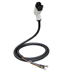
Buyers should also evaluate the relationship between the CCS2 connector, cable conductor, strain relief, and terminal design as one integrated structure. High-current reliability depends on all of these components working together.
3. What OEM Buyers Should Check When Sourcing 250A CCS2 DC Charging Cables
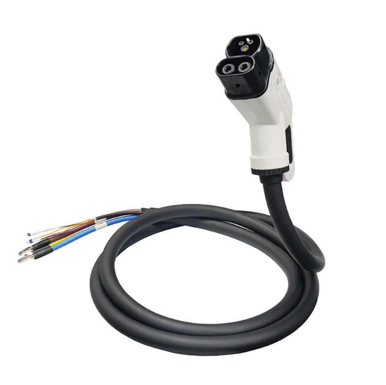
For charging station manufacturers and infrastructure operators, cable selection should be based on total electrical and thermal performance rather than only current rating. Two cables labeled for 250A operation may have very different resistance, temperature rise, flexibility, connector durability, and production consistency.
Conductor cross-sectional area
Total cable resistance
Voltage drop at rated current
Connector contact resistance
Temperature rise under 250A load
Terminal crimp consistency
Connector insertion durability
Cable flexibility and weight
Production traceability
Batch-to-batch consistency
Sample validation should reproduce realistic fast-charging conditions. Engineers should monitor voltage at the charger output and vehicle-side connection while measuring temperature at the cable, terminal, and connector contact areas. Longer-duration testing is useful because some thermal problems only appear after the assembly reaches a stable operating temperature.
Supplier manufacturing capability is equally important. Variations in conductor stranding, terminal crimping, contact machining, surface plating, cable extrusion, and connector assembly can influence total resistance. For large charging network projects, these variations may create inconsistent performance across multiple charging points.
Customization capability may also be valuable. Different charging stations can require different cable lengths, mechanical structures, communication wiring, strain relief, connector orientation, or environmental performance. An experienced supplier can help balance conductor size, thermal performance, flexibility, and cost for the intended charging platform.
Procurement teams should therefore compare lifecycle value rather than only cable price. Lower voltage drop can reduce wasted energy, while stable contact resistance and lower thermal stress can help reduce maintenance, connector replacement, and field failure risk over the service life of the charging equipment.
Conclusion
Conductor size and contact design have a direct impact on voltage drop, heat generation, efficiency, and long-term reliability in 250A CCS2 DC charging cables. Larger and well-designed conductors can reduce cable resistance, while stable low-resistance contacts and high-quality terminal connections help prevent localized hot spots at the connector. For OEM charger manufacturers and procurement teams, the best cable should be evaluated according to total resistance, voltage drop, temperature rise, contact quality, mechanical durability, manufacturing consistency, and user handling requirements. By selecting a supplier that can control both conductor construction and connector contact design, charging equipment manufacturers can improve power delivery efficiency and build more reliable high-current fast-charging systems.