How Meter Shunt Geometry Affects Anti-Magnetic Design and Terminal Assembly in Smart Meters
How Meter Shunt Geometry Affects Anti-Magnetic Design and Terminal Assembly in Smart Meters
Meter shunt resistors are essential current-sampling components in many smart meter architectures. Although resistance value and temperature coefficient receive most of the attention during sourcing, the physical geometry of the shunt can be equally important. The location of the resistance alloy, terminal shape, conductor path, mounting structure, and sensing position can influence magnetic-field exposure, heat distribution, terminal assembly, PCB layout, and calibration consistency. For smart meter OEMs and procurement teams, selecting the right shunt geometry can therefore reduce integration risk while supporting more stable high-current measurement and more efficient mass production.
1. Shunt Geometry Can Influence Magnetic Exposure and Current Measurement Stability
A meter shunt measures current by creating a small voltage drop across a precisely controlled low-resistance element. Because the measured voltage is very small, the complete current path needs to remain stable and repeatable. In smart meter designs where magnetic-field resistance is an important requirement, the physical arrangement of the shunt and surrounding conductors deserves careful attention.
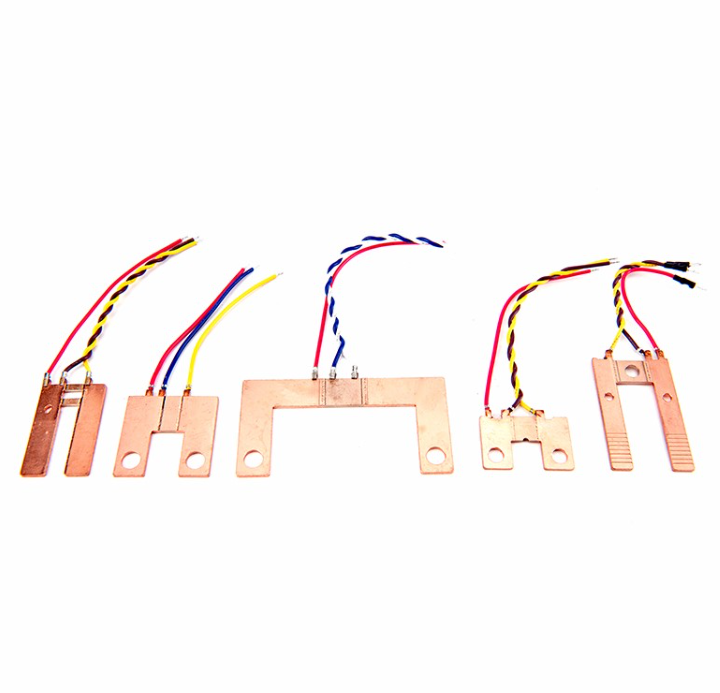
High current flowing through conductors and terminals creates magnetic fields. The geometry of the current path determines how those fields are distributed around the shunt, metering circuit, and nearby sensing components. A compact and well-controlled current path can help designers reduce unnecessary loop area and manage the relationship between the shunt, terminals, busbars, and PCB.
Position of the resistance alloy relative to high-current conductors
Distance between current and voltage-sensing paths
Terminal spacing and conductor routing
Orientation of the shunt inside the meter enclosure
Busbar shape and current-loop area
Location of nearby magnetic or metering components
In anti-magnetic meter designs, the objective is not simply to change the shunt resistance value. Mechanical layout and conductor geometry can help the engineering team reduce sensitivity to unwanted magnetic influence and maintain a more predictable voltage-sensing path.
For procurement teams, this means two shunts with the same nominal resistance may not be interchangeable. Their geometry can affect how easily they fit into the meter's anti-magnetic layout and how much redesign is required around the terminal and PCB structure.
2. Terminal Geometry Directly Affects Assembly Efficiency, Heat Distribution and Calibration
Meter shunts are often integrated directly into the terminal and busbar structure of the energy meter. The terminal shape, mounting holes, conductive section width, and sensing-point position can therefore influence both electrical performance and production efficiency.
A shunt designed around the meter's terminal structure can reduce the number of additional busbar parts, connection points, and manual assembly operations. This is especially valuable in high-volume production where small improvements in assembly time can create meaningful cost savings.
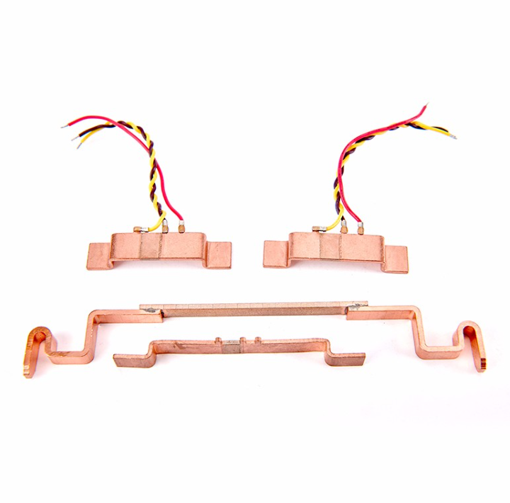
Proper geometry allows the shunt to integrate more naturally with screw, cage-clamp, or busbar terminal structures.
Consistent mounting points and dimensions help reduce operator-dependent assembly differences.
Balanced conductive geometry can help avoid localized hot spots during continuous high-current operation.
Proper voltage-sensing locations can reduce unwanted influence from terminal and connection resistance.
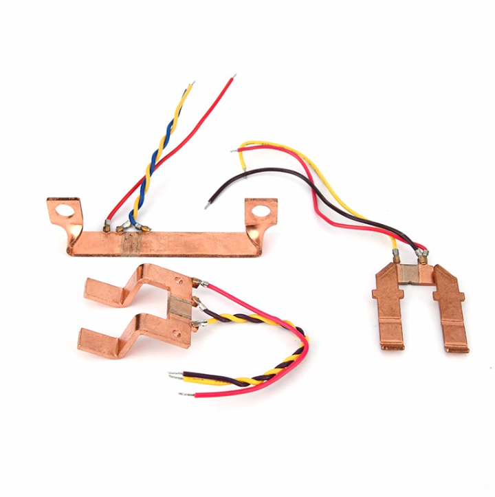
Different meter architectures may require different shunt structures. One design may suit a conventional terminal block, while another may be optimized for a cage-clamp terminal or a compact anti-magnetic layout. For this reason, OEM buyers should not treat shunt geometry as a cosmetic difference.
The position of the manganin or other resistance alloy is also important. If the sensing element is too close to a high-resistance joint or poorly positioned relative to the sense points, calibration consistency may be affected. Stable geometry helps the measurement circuit sample the intended voltage drop more repeatably.
For high-current meters, thermal behavior must also be considered. Wider conductive sections, terminal thickness, mounting pressure, and heat flow into surrounding copper parts all influence operating temperature. A mechanically convenient shunt that creates excessive thermal concentration may introduce drift or reduce long-term reliability.
3. What OEM Buyers Should Check When Selecting Meter Shunt Structures
Once the shunt geometry has been integrated into the terminal assembly, PCB layout, enclosure, and calibration process, changing the structure later can be expensive. Procurement and engineering teams should therefore evaluate the shunt as part of the complete smart meter mechanical and electrical architecture.
Nominal resistance value
Resistance tolerance
Temperature coefficient
Terminal geometry
Sense-point positioning
Busbar compatibility
Anti-magnetic layout suitability
Temperature-rise performance
Dimensional consistency
Batch-to-batch repeatability
Buyers should assemble prototype shunts with the actual terminal block, PCB, enclosure, and conductor structure whenever possible. This allows engineering teams to evaluate mechanical fit, sense-wire routing, thermal behavior, magnetic layout, and calibration performance under realistic conditions.
Manufacturing consistency is particularly important. Small differences in resistance-alloy position, copper dimensions, welding position, mounting holes, or terminal flatness can influence both electrical performance and assembly efficiency. In high-volume smart meter production, these variations can increase calibration time and rework.
Supplier customization capability can therefore provide significant value. Different smart meter platforms may require different shunt widths, terminal shapes, cage-clamp interfaces, sensing positions, mounting structures, or resistance values. A supplier that can optimize the geometry around the complete meter can help reduce unnecessary additional parts and improve production standardization.
Procurement teams should also consider lifecycle cost rather than component price alone. A well-matched shunt geometry can simplify terminal assembly, reduce thermal and magnetic design compromises, improve calibration repeatability, and lower redesign risk across the entire smart meter program.
Conclusion
Meter shunt geometry can influence far more than mechanical fit. The shape and position of the resistance element, terminals, busbars, and sense points can affect magnetic-field exposure, terminal assembly, heat distribution, calibration stability, and overall smart meter reliability. For OEM designers and procurement teams, the best shunt structure should therefore be selected according to the complete meter architecture rather than resistance value alone. By working with a supplier that can provide stable dimensions, controlled welding, customized terminal geometry, and consistent mass production, smart meter manufacturers can improve anti-magnetic design, simplify assembly, reduce calibration variation, and build more reliable high-current metering products.