How PCB Mount Busbar Current Transformers Reduce Assembly Steps in Compact 40A Smart Meter Platforms
How PCB Mount Busbar Current Transformers Reduce Assembly Steps in Compact 40A Smart Meter Platforms
Compact smart meter platforms require manufacturers to fit current measurement, power supply, communication, display, switching, and protection functions into increasingly limited internal space. In this environment, the current transformer is not only a measurement component but also an important part of the mechanical assembly strategy. PCB mount busbar current transformers combine the primary busbar path and secondary PCB connection into a compact structure, helping reduce additional wiring, brackets, and manual positioning. For smart meter OEMs and procurement teams, this architecture can simplify assembly, improve production repeatability, and support more efficient high-volume manufacturing.
1. Integrated Busbar and PCB Mounting Can Reduce Manual Assembly Operations
In a conventional smart meter structure, the current transformer, primary conductor, secondary wires, PCB, and fixing parts may all be assembled separately. Each additional connection requires positioning, fastening, soldering, or inspection. When meter production reaches hundreds of thousands or millions of units, even one extra manual operation can increase labor cost and create more opportunities for assembly variation.
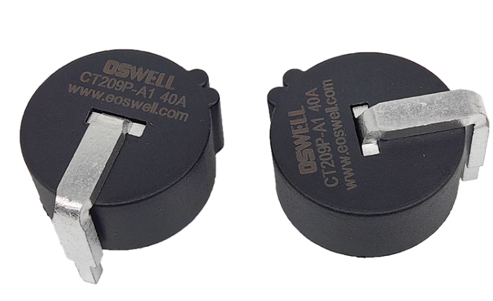
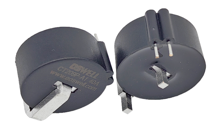
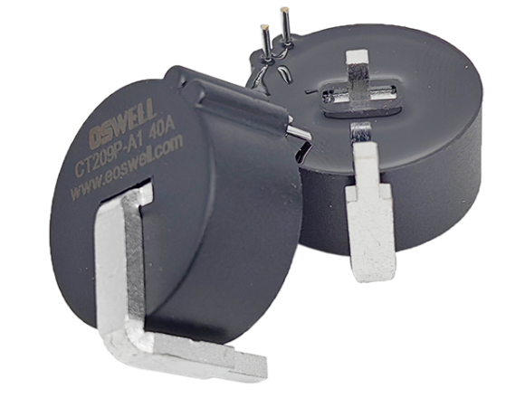
A PCB mount busbar CT can simplify this structure by integrating more of the current path and measurement connection into one component. The busbar passes through or forms part of the primary current path, while the secondary terminals can connect directly to the PCB.
Fewer secondary lead wires
Reduced soldering and connector operations
Less need for separate CT mounting brackets
More repeatable primary conductor positioning
Simplified PCB installation
Lower operator-dependent assembly variation
For compact 40A smart meters, these savings are particularly useful because internal space is limited. A more integrated current transformer structure can free space for communication modules, magnetic latching relays, LCD interfaces, power supplies, and other smart meter electronics.
Procurement teams should therefore compare total assembly complexity rather than looking only at the CT unit price. A slightly more integrated component may reduce labor, fixtures, wiring, inspection steps, and production errors across the complete meter assembly line.
2. Precise Mechanical Positioning Helps Improve Calibration and Measurement Consistency
Current transformer performance depends partly on the relationship between the primary conductor and the magnetic core. If the conductor position changes from one meter to another, small measurement differences may appear. Integrated busbar structures help manufacturers control this geometry more consistently during production.
Direct PCB mounting can also reduce variation in the secondary connection path. Instead of relying on manually routed wires, the CT output can connect to a defined PCB position, helping standardize the measurement circuit across every meter.
Controlled primary conductor geometry helps improve unit-to-unit measurement repeatability.
Fixed secondary terminals can reduce wiring variation and simplify signal routing to the metering circuit.
More consistent mechanical and electrical geometry can help reduce calibration differences between meters.
High measurement accuracy can be combined with a structure suitable for space-constrained smart meter platforms.
For 40A metering applications, buyers should evaluate ratio accuracy and phase displacement across the expected current range. Low-load accuracy can be just as important as full-load performance because smart meters frequently measure small household or commercial loads for long periods.
Secondary burden must also be considered. The CT, burden resistor, PCB traces, metering IC, and signal-conditioning circuit work as one system. Even an accurate CT can deliver lower system performance if the secondary circuit is poorly matched.
OEM engineers should therefore validate the transformer inside the actual meter PCB and busbar structure rather than relying only on standalone CT data.
3. What Procurement Teams Should Check Before Selecting a PCB Mount Busbar CT
Once the CT has been designed around the meter busbar and PCB, replacing it later can require mechanical redesign, new PCB routing, recalibration, and changes to production fixtures. Procurement teams should therefore evaluate both electrical performance and manufacturing consistency before approving a component for mass production.
40A rated current capability
Ratio accuracy
Phase displacement
Secondary burden requirements
Busbar dimensions
PCB pin position and tolerance
Temperature stability
Mechanical mounting accuracy
End-of-line testing capability
Batch-to-batch consistency
Dimensional tolerance deserves special attention because the component must fit both the primary current path and PCB. Small variations in pin location, housing size, or busbar geometry can create problems in automated insertion or final meter assembly.
Procurement teams should also ask how the supplier controls magnetic core materials, winding turns, busbar position, solderable terminals, and final electrical testing. For a high-accuracy 40A CT, small manufacturing differences can affect both measurement performance and assembly efficiency.
Sample validation should include several units assembled onto the actual meter PCB. Engineers can evaluate insertion fit, soldering quality, busbar alignment, temperature rise, calibration variation, and performance across low, medium, and rated current levels.
Total lifecycle value should therefore include more than the CT purchase price. Reduced assembly operations, lower wiring complexity, faster calibration, improved first-pass yield, easier automation, and more stable long-term supply can all make an integrated PCB mount busbar CT more economical over the complete smart meter production cycle.
Conclusion
PCB mount busbar current transformers can reduce assembly steps in compact 40A smart meter platforms by combining a controlled primary current path with direct secondary PCB connection. This integrated architecture can reduce lead wires, mounting hardware, manual alignment, and assembly variation while supporting more repeatable calibration and automated production. For OEM manufacturers and procurement teams, the best solution should be evaluated according to accuracy, phase performance, burden matching, busbar compatibility, PCB tolerances, temperature stability, and mass-production consistency. By selecting a well-designed PCB mount busbar CT and a supplier with strong manufacturing control, smart meter manufacturers can simplify assembly while improving product consistency and long-term metering reliability.