Latching Relay with Shunt vs Current Transformer: Which Integrated Architecture Is Better for Smart Meter Design?
Latching Relay with Shunt vs Current Transformer: Which Integrated Architecture Is Better for Smart Meter Design?
Modern smart meter manufacturers are increasingly looking for integrated components that combine load switching and current measurement in a more compact structure. Two common approaches are a magnetic latching relay integrated with a shunt resistor and a latching relay integrated with a current transformer. Both architectures can reduce component count and simplify meter assembly, but they offer different advantages in measurement method, isolation, thermal behavior, PCB layout, and system cost. For OEM designers and procurement teams, choosing the right architecture depends on the complete smart meter design rather than on relay current rating alone.
1. How Shunt-Based and CT-Based Integrated Relay Architectures Differ
A magnetic latching relay performs the main load switching function inside a smart meter. Because it only requires energy during switching and does not need continuous coil power to maintain its position, it is widely used in modern electricity meters. When current measurement components are integrated into the relay assembly, manufacturers can reduce the number of independent parts inside the meter.
A relay with an integrated shunt resistor measures current by creating a very small voltage drop across a precision low-resistance element. The metering circuit reads this voltage and calculates the current flowing through the meter. This architecture can provide a compact current path and is attractive when the design requires direct current sampling and efficient use of internal space.
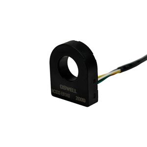
A relay with an integrated current transformer uses magnetic coupling to measure AC current. The primary current passes through the CT magnetic structure, while the secondary output is electrically isolated from the high-current path. This architecture can be attractive when isolation between the current path and metering electronics is an important design objective.
Shunt: direct resistive current measurement
CT: magnetic AC current measurement
Shunt: compact current path and direct voltage output
CT: inherent electrical separation between primary and secondary
Shunt: thermal behavior must be carefully controlled
CT: magnetic core accuracy and phase performance become important
For smart meter manufacturers, neither architecture is automatically better. The correct choice depends on the metering circuit, isolation strategy, available installation space, target current range, calibration approach, and overall cost structure.
2. Accuracy, Thermal Performance and Integration Determine the Better Choice
Procurement teams should avoid selecting an integrated relay based only on lower unit cost. Current measurement performance and system integration can affect calibration time, PCB complexity, temperature rise, production yield, and long-term meter reliability.
Shunts depend on resistance tolerance and temperature coefficient, while CTs depend on ratio accuracy, phase error, and magnetic consistency.
Shunts generate measurable heat under high current, making resistance stability and heat dissipation important design factors.
CT-based measurement provides magnetic isolation, which can simplify some low-voltage metering circuit architectures.
Integrated relay modules can reduce separate components, wiring steps, mounting points, and assembly variation.
Shunt-based designs are often attractive when compact structure, direct measurement, and low component count are important. However, the shunt resistance element must remain stable as temperature changes. Terminal resistance, welding quality, conductor geometry, and heat distribution can all influence the measurement signal.
CT-based designs can reduce the need for direct electrical connection between the current measurement output and the primary power path. However, the CT must maintain stable ratio and phase performance across the intended load range. Core material, winding consistency, DC bias conditions, and temperature can all influence final accuracy.
Products such as an integrated magnetic latching relay with a precision shunt and a latching relay combined with a current transformer represent two different ways to reduce the number of separate components in smart meter design. OEM teams should evaluate both options at system level rather than treating the current measurement element as an isolated component.
3. What Procurement Teams Should Compare Before Approving an Integrated Relay Solution
Once an integrated relay and current measurement architecture has been designed into a smart meter, changing it later may require modifications to the PCB, busbar, enclosure, calibration process, metering algorithm, and production fixtures. For this reason, procurement teams should qualify both the component design and the supplier before moving into mass production.
Rated switching current
Contact resistance
Temperature rise
Measurement accuracy
Thermal drift
Electrical isolation requirements
PCB and busbar compatibility
Mechanical dimensions
Calibration repeatability
Batch-to-batch consistency
For a shunt-integrated relay, buyers should review resistance tolerance, temperature coefficient, welding consistency, sense-point design, and heat distribution under continuous current. For a CT-integrated relay, important factors include current ratio, phase error, magnetic core consistency, winding quality, and performance across the meter's operating current range.
Relay performance itself remains equally important. Contact resistance, switching endurance, terminal construction, latching stability, and temperature rise should be tested together with the current measurement section. An integrated product only provides real value when both switching and measurement functions remain stable throughout the expected meter service life.
Procurement teams should also consider production economics. An integrated relay may reduce the number of individual components, assembly steps, soldering points, busbar connections, and inspection operations. This can simplify the BOM and improve high-volume production efficiency, even when the integrated component itself has a higher unit price.
Supplier customization capability is another important factor. Different smart meter platforms may require different current ratings, terminal structures, resistance values, CT ratios, mechanical dimensions, or mounting configurations. A supplier that can support mechanical and electrical customization may help the OEM reduce redesign work and improve platform standardization.
The final sourcing decision should therefore consider total lifecycle value, including component cost, calibration, assembly labor, production yield, thermal performance, field reliability, engineering support, and long-term supply stability.
Conclusion
A latching relay integrated with a shunt resistor and a latching relay integrated with a current transformer can both simplify smart meter architecture, but they solve the current measurement challenge in different ways. Shunt-based designs can offer compact direct current sensing and efficient component integration, while CT-based designs provide magnetic measurement with electrical separation between the primary current path and metering electronics. For OEM designers and procurement teams, the better architecture depends on accuracy targets, thermal management, isolation requirements, mechanical space, calibration strategy, assembly efficiency, and total lifecycle cost. By evaluating switching performance and current measurement as one integrated system, smart meter manufacturers can select a solution that reduces component count while improving production consistency and long-term product reliability.