Why Burden Matching Matters in 1000A 0.1 Class Clip-On Current Clamp Measurement
Why Burden Matching Matters in 1000A 0.1 Class Clip-On Current Clamp Measurement
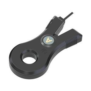
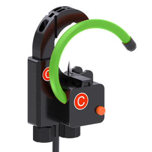
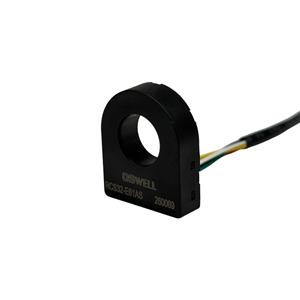
A 1000A 0.1 class clip-on current clamp can provide highly accurate, non-intrusive current measurement for industrial energy monitoring, power quality equipment, electrical testing, and energy auditing. However, the accuracy printed on the clamp specification does not automatically guarantee the same accuracy at system level. The secondary burden, connecting cable, meter input, and complete measurement circuit all influence the operating point of the current transformer. For OEM equipment manufacturers and procurement teams, correct burden matching is therefore essential for maintaining ratio accuracy, phase performance, thermal stability, and repeatable measurement in real installations.
1. Why the Secondary Burden Changes the Real Accuracy of a Current Clamp
A clip-on current clamp based on current transformer technology converts a large primary current into a smaller secondary current that can be measured safely by an instrument. In a 1000A/1A configuration, the secondary side must operate within the electrical conditions for which the transformer was designed.
The total impedance connected to the secondary is known as the burden. It includes not only the input of the measuring instrument, but also lead-wire resistance, connectors, terminals, protection components, and any additional resistance in the signal path.
When the burden becomes too high, the current transformer must generate a larger secondary voltage to drive the required secondary current. This increases magnetic flux in the core and may cause ratio error and phase displacement to rise. In demanding conditions, the core may move closer to saturation, reducing the accuracy advantage expected from a 0.1 class device.
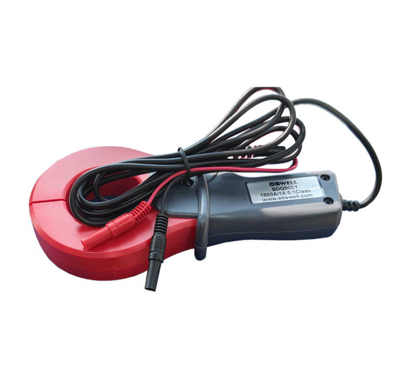
Measurement instrument input impedance
Secondary cable resistance
Connector and terminal resistance
Burden resistor values
Protection circuit components
Additional wiring inside the monitoring equipment
For procurement teams, this means selecting a 0.1 class clamp should never be based on accuracy class alone. Buyers need to understand the complete secondary circuit and confirm that the clamp is operating within its specified burden conditions.
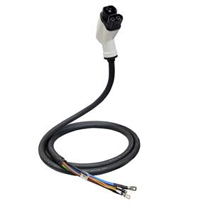
This is especially important when longer secondary cables are required. Increasing cable length increases resistance, which directly adds to the total burden. A measurement system that works correctly with a short laboratory lead may behave differently after installation several meters away from the monitoring device.
2. Proper Burden Matching Protects Ratio Accuracy, Phase Performance and Energy Measurement Quality
For a professional energy monitoring system, current magnitude is only part of the measurement requirement. Phase performance is also important because power meters calculate active power, reactive power, power factor, and energy by comparing voltage and current signals.
An unsuitable secondary burden can influence both ratio error and phase displacement. Even when the current reading appears close to the expected value, additional phase error can reduce the accuracy of calculated power and energy data.
Correct burden helps maintain a predictable relationship between primary and secondary current.
Controlled secondary loading helps reduce phase displacement that can affect power and energy calculations.
Avoiding excessive burden reduces unnecessary core excitation and helps maintain linear operation.
A standardized burden helps different monitoring units deliver more comparable measurements.
This becomes particularly important in energy audits, industrial load monitoring, data centers, factories, and commercial distribution systems where small measurement errors can influence efficiency calculations across many circuits.
OEM manufacturers should therefore calculate the complete secondary-loop impedance during equipment design. Cable gauge, cable length, connector structure, and instrument input characteristics should all be defined before the current clamp is approved.
Engineers should also validate the complete measurement chain at several primary current levels instead of testing the clamp independently. This allows the team to identify whether burden-related error increases at high current or changes across the operating range.
3. What OEM Buyers Should Check When Sourcing 1000A 0.1 Class Clip-On Current Clamps
For procurement teams, a high-accuracy clamp should be evaluated as part of a measurement system rather than as a standalone sensor. Once the clamp, cable, connector, and instrument architecture have been defined, changing one element may alter the total burden and require additional validation.
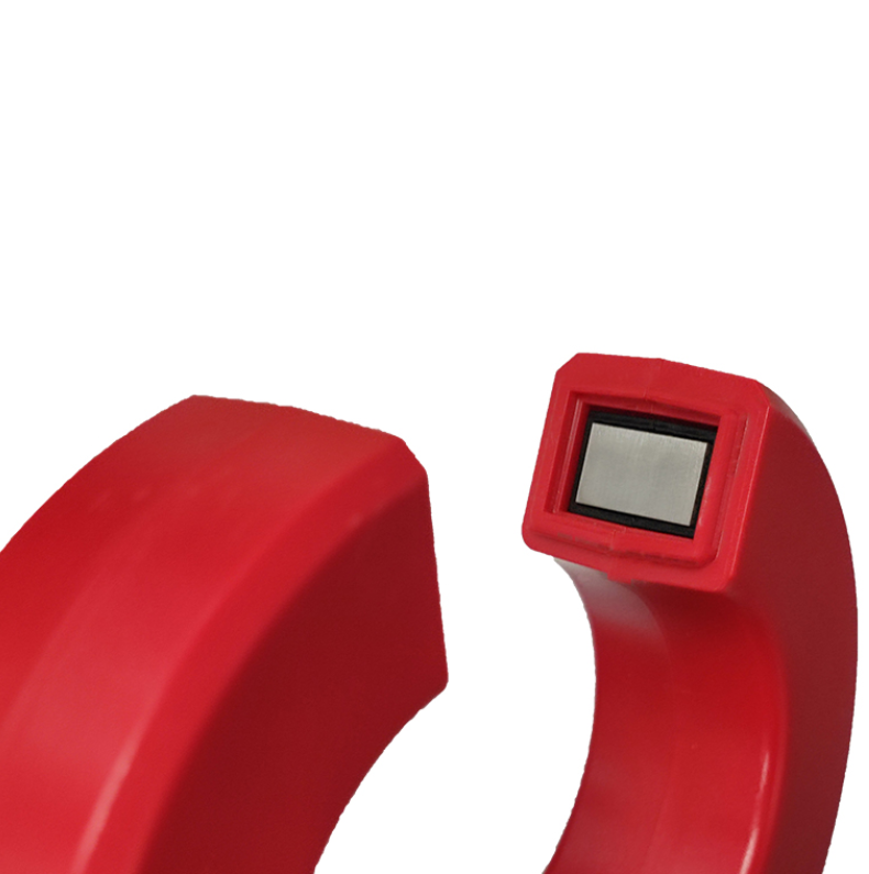
Primary and secondary current ratio
Accuracy class
Permitted secondary burden
Ratio error across the current range
Phase displacement
Secondary cable resistance
Core closing repeatability
Temperature stability
Mechanical clamp durability
Batch-to-batch consistency
Buyers should provide the sensor supplier with information about the actual measurement equipment, expected cable length, connector configuration, and operating current range. This allows the supplier to confirm whether the selected clamp is suitable for the intended burden instead of relying on a generic catalog selection.
Mechanical construction must also be considered. Clip-on sensors are repeatedly opened and closed, so core alignment and locking pressure need to remain stable. Even perfect burden matching cannot compensate for a magnetic core that does not close consistently.
For high-volume OEM projects, buyers should test multiple production samples with the same secondary load used in the final equipment. Comparing ratio and phase performance across samples can reveal manufacturing variation that may not be visible from a single prototype.
Total lifecycle cost is another important consideration. A lower-cost clamp may provide limited value if the design requires additional calibration, shorter cables, repeated field adjustment, or frequent replacement. A well-matched sensor with stable burden performance can reduce commissioning time, improve measurement consistency, and simplify long-term system maintenance.
Conclusion
Burden matching is essential for obtaining the expected performance from a 1000A 0.1 class clip-on current clamp. The clamp, secondary wiring, connectors, burden components, and measurement instrument form one electrical system, and excessive impedance can increase ratio error, phase displacement, magnetic stress, and overall measurement uncertainty. For OEM engineers and procurement teams, the best sourcing decision should therefore consider permitted burden, cable resistance, phase accuracy, current range, core closing consistency, temperature stability, and production repeatability together. By matching the current clamp to the actual measurement circuit before mass production, manufacturers can preserve high-accuracy performance and build more reliable industrial energy monitoring equipment.