How To Choose Between Shunt Resistors And Current Transformers For Different Smart Meter Designs
How To Choose Between Shunt Resistors And Current Transformers For Different Smart Meter Designs
In smart meter design, choosing the right current sensing method is one of the most important technical and commercial decisions. Two of the most widely used solutions are the shunt resistor and the current transformer. Both can measure current, but they behave very differently in terms of cost, isolation, thermal performance, integration method, and long-term application suitability. This guide explains how to choose between shunt resistors and current transformers for different smart meter designs so buyers and engineers can match the right sensing method to the real project requirement.
1. Why Smart Meter Designers Compare Shunts And CTs So Often
In smart meter projects, the current sensing path directly influences measurement structure, product cost, PCB layout, thermal control, and long-term stability. This is why the choice between a shunt resistor and a current transformer is not just a component comparison. It is a system-level design decision. A project that uses the wrong sensing method may still work in early samples, but later face problems in calibration, assembly, thermal performance, or overall meter consistency.
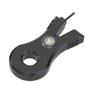
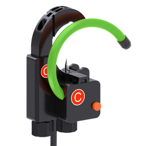
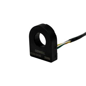
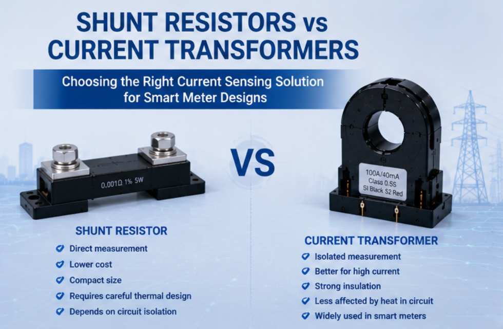
A shunt resistor measures current by creating a small voltage drop across a precision resistance element. The meter reads that voltage and calculates the current. This approach is direct and often attractive in cost-sensitive or compact meter designs. A current transformer works by electromagnetic induction and provides a different kind of sensing path, one that is often favored where isolation structure or certain metering behaviors are more important.
Because these two sensing methods are based on different principles, they do not create the same design conditions inside the meter. A shunt may be the better choice in one project and a CT may be clearly better in another. The key is not to ask which method is generally better, but which method is better for the specific smart meter design being developed.
The strongest choice comes from matching the sensing method to the meter’s cost target, electrical architecture, thermal conditions, safety concept, and long-term production plan.
2. How These Two Methods Differ In Real Smart Meter Designs
The first major difference is cost orientation. In many smart meter designs, especially where the structure is simpler and cost sensitivity is higher, a shunt resistor can be an attractive option. It is often chosen when the project needs a more economical solution and the design team is prepared to manage the related circuit and thermal considerations carefully. A current transformer may carry a higher part cost in some cases, but that does not automatically make it the more expensive project choice if it reduces other risks in the overall design.
The second difference is isolation concept. A CT naturally supports an isolated sensing structure because of its electromagnetic working principle. This can be valuable in smart meter designs where electrical separation is an important part of the architecture. A shunt resistor is a direct conductive element, so it must be considered within the total circuit safety design. In some projects this is completely manageable, but in others the CT structure may be more suitable.
The third difference is thermal behavior. A shunt resistor is directly in the current path, so it can introduce heat that needs to be managed carefully inside the smart meter enclosure. This affects not only the shunt itself but also nearby components and long-term measurement stability. A current transformer follows a different thermal profile and may offer advantages where direct conductive heating is a bigger concern.
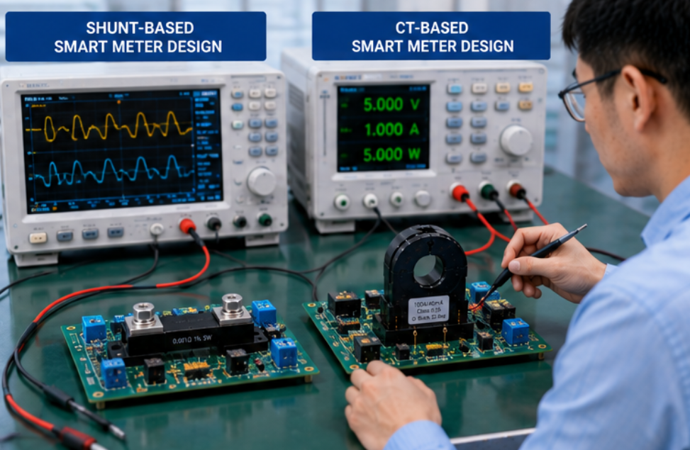
The fourth difference is integration style. A shunt resistor can be very effective in compact and direct-sensing architectures. A current transformer may be more suitable in designs where the team wants a magnetic sensing route, more natural isolation behavior, or a CT-based metering path that already aligns with the product platform. Neither method is automatically better. The fit depends on the real design condition.
This is why project teams should evaluate current sensing methods from a full design perspective instead of only comparing one line in a data sheet.
| Comparison Item | Shunt Resistor | Current Transformer |
|---|---|---|
| Working Principle | Measures current through voltage drop across resistance | Measures current through electromagnetic induction |
| Cost Orientation | Often more suitable for economical current sensing paths | May suit projects where structural advantages justify the choice |
| Isolation Characteristic | Depends on the overall circuit safety architecture | Naturally supports an isolated sensing structure |
| Thermal Consideration | Requires careful heat management in compact designs | Different thermal profile, often less direct conductive heating impact |
| Integration Style | Direct sensing path, good fit for some compact architectures | Magnetic sensing path, good fit for some isolation-oriented architectures |
| Typical Design Priority | Economy, direct sensing, compact structure | Isolation-related advantages, metering robustness, CT-based design route |
3. Which Method Is Better For Different Smart Meter Designs
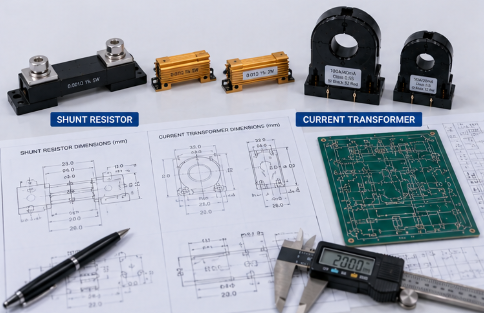
A shunt resistor is often the better choice when the smart meter design is strongly cost-driven, the current sensing path is intended to be direct, and the engineering team is comfortable managing the thermal and safety structure carefully. This is often attractive in designs where compactness and economy are important and the total circuit architecture is already aligned with shunt sensing.
A current transformer is often the better choice when the project places more importance on a magnetic sensing path, natural isolation-related advantages, or a product architecture that is already designed around CT-based metering. It can also be a stronger fit in projects where the team wants a sensing method that aligns with specific long-term metering preferences or application robustness goals.
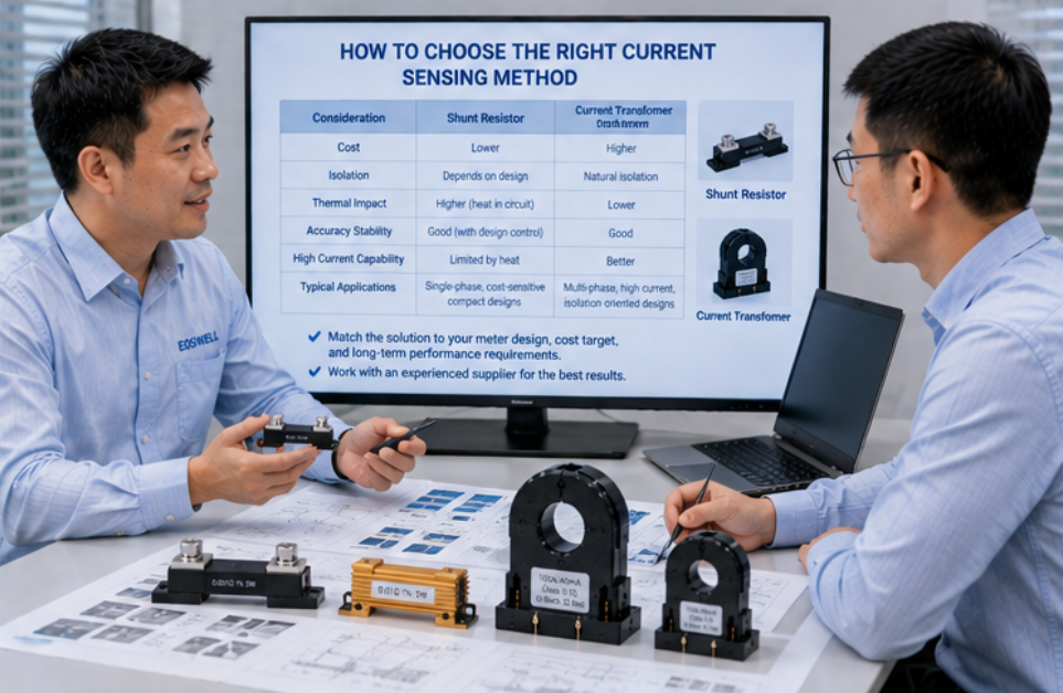
Buyers should also think beyond the sample. A sensing method that looks cheaper in the first comparison may still cost more later if it increases calibration difficulty, thermal design pressure, or production variation. Likewise, a method that looks slightly higher in component cost may still be the better project choice if it supports smoother integration and lower future risk.
Another important point is supplier capability. Whether the project uses a shunt or a CT, the supplier should be able to maintain stable production control, repeatable quality, and useful technical support. A good sensing method can still become a weak project choice if the supply side is unstable.
The best decision usually comes from matching the sensing method to the actual smart meter design target instead of trying to apply one rule to every project. That is the most practical way to choose correctly.
Conclusion
Choosing between shunt resistors and current transformers for different smart meter designs requires more than a simple cost comparison. The right method depends on the project’s current sensing architecture, safety structure, thermal strategy, integration style, and long-term production plan. When buyers and engineers evaluate these factors together, they can choose a sensing method that supports not only the design target, but also smoother OEM execution and lower future risk.
Contact Us
Looking for the right current sensing solution for your smart meter project? Contact our team to discuss your design, sampling needs, and quotation details.